
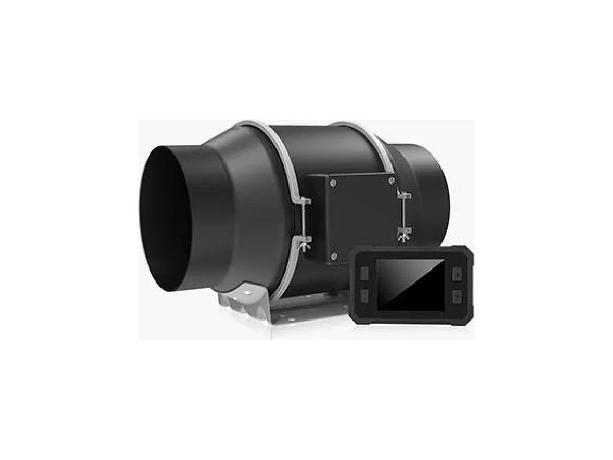
An EC fan is compatible with an OEM control system only when its actual command input, wiring, feedback and fault behavior match the controller and project requirements. A label such as 0–10 V, PWM or Modbus is a starting point, not proof of compatible signals, settings or operating limits.
Map the fan, controller and BMS architecture
Document which device sets fan speed, which device monitors it, and how the building management system (BMS) connects. For example, the OEM controller might send the fan command while the BMS sends a supervisory request to the OEM controller. Define who has command priority, whether a local override is permitted, and how interlocks affect operation. Avoid assigning two controllers as independent command sources unless the control design specifies how conflicts are resolved.
CZJ’s listed EC motor and backward-curved centrifugal fan options name 0–10 V, PWM and Modbus. Confirm which interface applies to the exact proposed model and configuration, and whether these are alternatives or available together. A product page for an EC inline duct fan with a variable-speed dial describes a local control; do not treat that detail as confirmation of an external OEM input.
Confirm the signal, wiring and limits
For an analog input, request the accepted voltage range, input reference and wiring diagram. Confirm whether zero command stops the fan or sets a minimum speed, and identify any minimum, maximum or enable requirements. For PWM, ask for the signal voltage or logic thresholds, frequency range, polarity, duty-cycle mapping and stop behavior. These details determine whether the controller output can drive the fan input directly.
For Modbus, confirm the physical interface, protocol mode, communication settings, device addressing and register-map revision. Request register definitions, units, scaling, writable points and timeout behavior. Do not assume that a Modbus label establishes the transport, register map or compatibility with the OEM controller.
| Requirement | Request before purchase | Verify during integration |
|---|---|---|
| Command input | Signal range, reference, polarity and stop/minimum-speed behavior | Test the controller output at defined low, middle and high commands |
| Wiring | Pinout, required common, shielding and any isolation requirements | Check continuity, polarity and grounding against the approved diagram |
| Modbus | Interface, settings, register map, units and writable points | Read status, write a command and confirm the reported response |
| Operating limits | Permitted command range and any limits or enable conditions | Confirm operation at the agreed limits without exceeding the approved duty |
Specify feedback and diagnostics
Separate the commanded speed from measured speed. Ask whether the exact model provides actual RPM, a speed-proportional signal, run or ready status, fault output, or communication-register diagnostics. For each available point, request its electrical or protocol definition, scaling, update behavior and meaning. A controller that displays its own requested speed does not thereby confirm the fan reached that speed.
Add required feedback points to the I/O list and controller sequence. If a fault code or status bit is required for service, request its definition and the conditions that set and clear it. The industrial fan RFQ checklist can help organize interface details with the other items in the purchase specification.
Define behavior when a signal fails
Specify the expected response to an open or invalid analog command, loss of PWM, communication timeout, fan fault, and loss or restoration of power. Possible responses include stopping, holding a defined command, or operating at a defined fallback setting; none should be assumed without agreement for the selected model and system. Also state whether the fan may restart automatically after power or communication returns, and which interlocks must be satisfied first.
A network command should not be assumed to provide a safety shutdown. Where shutdown protects people, equipment or process, define the required interlock and shutdown behavior in the system design and verify the actual fan arrangement supports it.
Approve commissioning with the airflow-pressure duty
Make the control acceptance plan part of the same approval as the fan selection. State the required airflow and pressure basis, operating conditions and installation arrangement. Static pressure, velocity pressure and total pressure describe different quantities; fan static pressure is a defined fan rating basis, not simply any difference between two duct static taps. The controller’s output percentage is not evidence that the required duty has been met. Compare the fan selection and field measurements on the same pressure basis and arrangement. See fan technical specifications explained for the distinction between airflow, pressure and power terms.
Use a written test matrix that records the command, expected response, feedback and pass criterion. Include startup, several agreed command points, any configured minimum and maximum, each required status or fault indication, communication loss, power interruption and approved restart conditions. Record measured airflow and pressure at the agreed duty point; treat current as an electrical check, not proof of input power or airflow.
FAQ
Does a Modbus label confirm compatibility with my controller?
No. Confirm the physical interface, protocol mode, communication settings, register map, units, writable commands and fault behavior for the exact fan configuration. Test command and feedback exchange with the intended controller before approving the interface.
Can I use the same commissioning test for every fan model?
Use the same project acceptance criteria where appropriate, but confirm the signal definitions, limits, feedback and fault behavior for each selected model. Test the installed arrangement at the required airflow and pressure duty.
What should I send with an EC fan inquiry?
Share the proposed airflow-pressure duty, supply details, controller make and interface, wiring or I/O requirements, requested feedback, failure responses, quantity, destination and relevant project documents. For project-specific review, discuss requirements and identify the exact control interface and acceptance tests you need approved.