
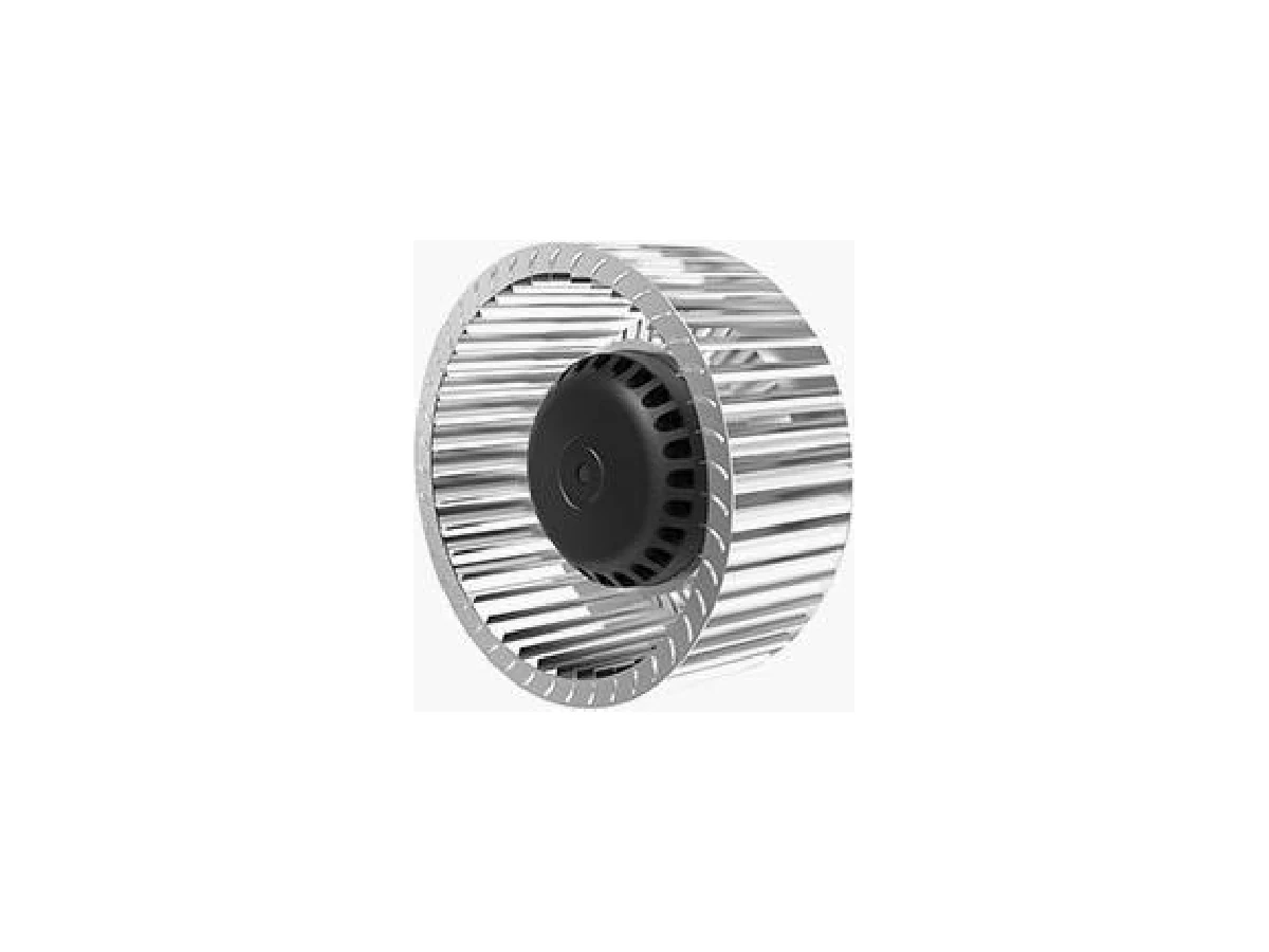
A replacement impeller must match the existing fan mechanically and operate correctly at the required speed and airflow. Before ordering, record the impeller diameter, width, hub, bore, keyway, rotation, material and drive arrangement, then ask the supplier to review the measurements against the complete fan assembly.
A diameter alone is not enough to establish interchangeability. Two wheels with the same outside diameter can have different blade geometry, inlet width, hub length, shaft interfaces or rotation requirements.
Record the Impeller and Hub Dimensions
Start with the removed part and the surrounding fan assembly. Clean the hub and measure with suitable tools, recording the units and the points between which each dimension was taken.
For a centrifugal impeller, record:
- Outside impeller diameter.
- Overall wheel width and blade width.
- Inlet diameter or inlet opening for a single-inlet wheel.
- Hub outside diameter and hub length.
- Bore diameter and the distance from the wheel face to the bore shoulder.
- Keyway width, depth and position, if present.
- Number of blades, blade form and approximate blade angle.
- Axial clearance to the inlet cone, housing and adjacent components.
For an axial impeller or blade assembly, record:
- Tip diameter or nominal fan diameter.
- Hub diameter and hub length.
- Number of blades.
- Blade pitch or pitch-adjustment arrangement.
- Blade root shape and attachment method.
- Overall axial projection and clearance to the guard or shroud.
- Bolt circle, pilot diameter and fastener size where the hub mounts to a shaft or motor.
Do not measure a damaged or distorted edge as the finished dimension. Compare several points around the circumference and note whether the part is worn, bent or out of round. A photograph with a ruler, a sketch with arrows and the original model plate can help the supplier interpret the measurements.
The available product options cover different geometries and sizes. For example, the backward curved centrifugal fan with mounting bracket lists an impeller diameter of 130-630 mm, while the AT Series belt-driven backward curved fan lists 280-1000 mm. These diameter ranges are selection information, not proof that a wheel will fit a particular housing or shaft.
Confirm Rotation, Airflow Direction and Mounting Arrangement
Identify rotation from the drive side and state the viewing direction. “Clockwise” without a viewing reference can be ambiguous. Mark the drive side, inlet side and discharge direction on your sketch or photograph.
For a centrifugal wheel, confirm:
- Rotation when viewed from the shaft or drive side.
- Single-inlet or double-inlet construction.
- Radial, forward-curved or backward-curved blade form.
- Housing discharge orientation and inlet arrangement.
- Whether the wheel is mounted inside a scroll housing, a cabinet or an open frame.
For an axial assembly, confirm the airflow direction through the fan and the rotation viewed from the specified side. A blade that physically mounts to the hub may still produce the wrong airflow direction or performance if its pitch or handedness is different.
The AC external rotor forward curved centrifugal fan wheel is a wheel option with a stated 140-300 mm diameter range and sheet steel or aluminum rim. The AC external rotor axial fan with protective guard is a complete axial fan option with a stated 200-800 mm fan diameter range. Treat these as different equipment arrangements: a complete fan unit is not automatically a replacement wheel for an existing assembly.
Also confirm how the part is supported. A direct external-rotor arrangement may integrate the motor with the fan assembly. A belt-driven fan normally uses a separate shaft, bearings, pulley and belt guard. Replacing only the wheel may therefore require a different hub or shaft interface even when the outer dimensions appear close.
Match Bore, Keyway and Shaft Interface
The bore is the most direct mechanical connection between a shaft and an impeller hub, but it is only one part of the interface. Ask the supplier to confirm the full shaft connection before approval.
Check the following details:
| Requirement | What to record from the existing assembly | How to verify the candidate part |
|---|---|---|
| Bore | Finished bore diameter, tolerance if known and bore depth | Compare the supplier drawing with a calibrated shaft or verified shaft measurement |
| Keyway | Key width, depth, length and angular position | Confirm the key standard or request a hub drawing showing the keyway |
| Hub location | Shoulder position, hub length and axial offset | Check the wheel sits at the original inlet and housing position |
| Mounting method | Keyed shaft, taper bush, clamp hub, set screw or flange | Match the actual shaft connection; do not assume a set screw replaces a key |
| Balance | Existing balance condition and any balance weights | Request confirmation of balancing method and inspect after installation |
| Clearance | Tip, inlet, backplate and housing clearances | Compare the complete assembly dimensions, not only the wheel diameter |
One listed high-volume centrifugal impeller provides a useful example of the information that should appear in a request: its product information states a 250-800 mm diameter range and a 19-48 mm bore with a keyed hub, with carbon steel or stainless steel listed as material options. Confirm the exact selected diameter, bore, keyway and hub drawing for the required part rather than treating the full range as one configuration.
For a belt-driven assembly, also record shaft diameter, pulley bore, pulley pitch diameter, belt section, shaft centerline and the required wheel position. A change in pulley ratio changes fan speed. A change in speed changes the operating point and power requirement, so the replacement should be checked against the system duty rather than fitted solely by physical dimensions.
For direct-drive equipment, confirm the motor shaft, rotor arrangement, mounting flange, electrical supply and control method. The absence of a belt does not mean that the complete system has no losses or that any motor can drive the replacement wheel. Motor output, shaft power and mains electrical input are different quantities; motor current alone does not establish the required airflow or fan power.
Check Material and Operating Conditions
Material selection depends on the air stream, temperature, moisture, contaminants, cleaning method and mechanical speed. State the operating conditions with the dimensions.
Provide:
- Normal and maximum air temperature.
- Air density if the application is at high altitude or the air is significantly heated.
- Dust, fibers, droplets, chemicals or corrosive vapors in the air stream.
- Continuous or intermittent duty and expected running speed.
- Washdown, outdoor exposure or condensation conditions.
- Whether the fan is installed in a hazardous area or handles combustible dust.
- Required noise, vibration and balance limits.
The listed aluminum axial impeller blade option states a 250-800 mm diameter range, high-strength die-cast aluminum construction and a stated temperature range of -40°C to +150°C. Those details apply to that product option and still require confirmation against the actual speed, mounting arrangement, air chemistry and duty. A material label by itself does not establish suitability for every process condition.
Other options list different materials. A standard AC backward-curved fan lists PA66 glass fiber or aluminum for the impeller, while the high-volume centrifugal impeller lists carbon steel or stainless steel. Ask which material applies to the quoted configuration and whether coatings, welds, inserts or balance weights alter the fit or service limits.
For corrosive or wet air, compare the complete wetted construction, not only the impeller material. The corrosion-resistant fan material guide can help structure that review. For hazardous locations, request the applicable equipment documentation and verify requirements with the responsible project authority; do not infer approval from a motor enclosure rating or insulation class.
Request a Fitment Review Before Ordering
Send the supplier a complete parts-level request. A practical review sequence is:
- Attach photographs of the removed impeller, hub, shaft, housing, motor or pulley arrangement and identification plate.
- Provide a dimensioned sketch covering diameter, width, hub, bore, keyway, bolt circle, offsets and clearances.
- State rotation, viewing direction, airflow direction, inlet arrangement and discharge orientation.
- Identify the drive type, shaft speed or pulley ratio, motor rating, electrical supply and control method.
- Provide design airflow and pressure on a defined basis, together with air temperature, density and operating altitude.
- Ask for a drawing of the proposed impeller and a written list of assumptions before authorizing production or shipment.
- Confirm whether the proposal is an impeller only, a wheel-and-hub assembly, or a complete fan unit with housing and drive.
For performance review, compare the same pressure basis and installation arrangement. Fan static pressure, velocity pressure and total pressure are not interchangeable. A pressure difference measured at static taps is not generally the fan total pressure unless the measurement locations and definitions match the supplier’s data. The fan technical specifications guide explains the information that should accompany a performance comparison.
If ductwork, filters, dampers or inlet conditions have changed, the original wheel may no longer operate at the original duty. The system curve and fan operating point should be recalculated; fan similarity laws require comparable geometry, air density, efficiency and corresponding operating-point assumptions. The speed cube relationship is not a universal electrical saving percentage.
Fitment Review Checklist
Before placing the order, confirm that the supplier has addressed:
- Exact wheel or blade diameter and width.
- Bore, keyway, hub length and axial position.
- Rotation and airflow direction from a stated viewing side.
- Blade form, blade count and inlet arrangement.
- Drive type, speed, pulley details or motor interface.
- Material and operating temperature or contamination limits.
- Balance, clearance and proposed drawing approval.
- Quantity, destination and whether the replacement is part-only or a complete assembly.
FAQ
Can I order a replacement impeller using only the fan diameter?
No. Diameter is an initial filter, not a fitment decision. Confirm width, hub, bore, keyway, blade geometry, rotation, mounting position and clearance. The supplier should review the complete assembly and proposed drawing.
Can a centrifugal impeller from a different fan model be used if the bore matches?
Not automatically. Matching the bore does not confirm the blade geometry, wheel width, rotation, inlet relationship, balance or performance. A different wheel can change airflow, pressure, noise and shaft power even when it mounts on the same shaft.
Is a complete axial fan interchangeable with an axial impeller blade?
No. A complete axial fan includes a motor, hub, blade arrangement, guard or frame and mounting details. A replacement blade or impeller must match the hub interface, pitch, rotation, clearance and speed of the existing assembly.
What should I send for a supplier fitment check?
Send the original model information, clear photographs, a dimensioned sketch, bore and keyway measurements, rotation and airflow direction, drive details, operating conditions, required quantity and destination. Include the existing project duty if the replacement must reproduce a known airflow and pressure.
Procurement Brief
For a fitment review, share the proposed product or model reference, measured replacement fan impeller dimensions, quantity, destination, photographs, dimensioned drawings, rotation, bore and keyway details, drive arrangement, required airflow and pressure, air temperature, material requirements and any existing project documentation. For a structured request, see the industrial fan RFQ checklist, then discuss requirements with the measurements and assembly details ready.