
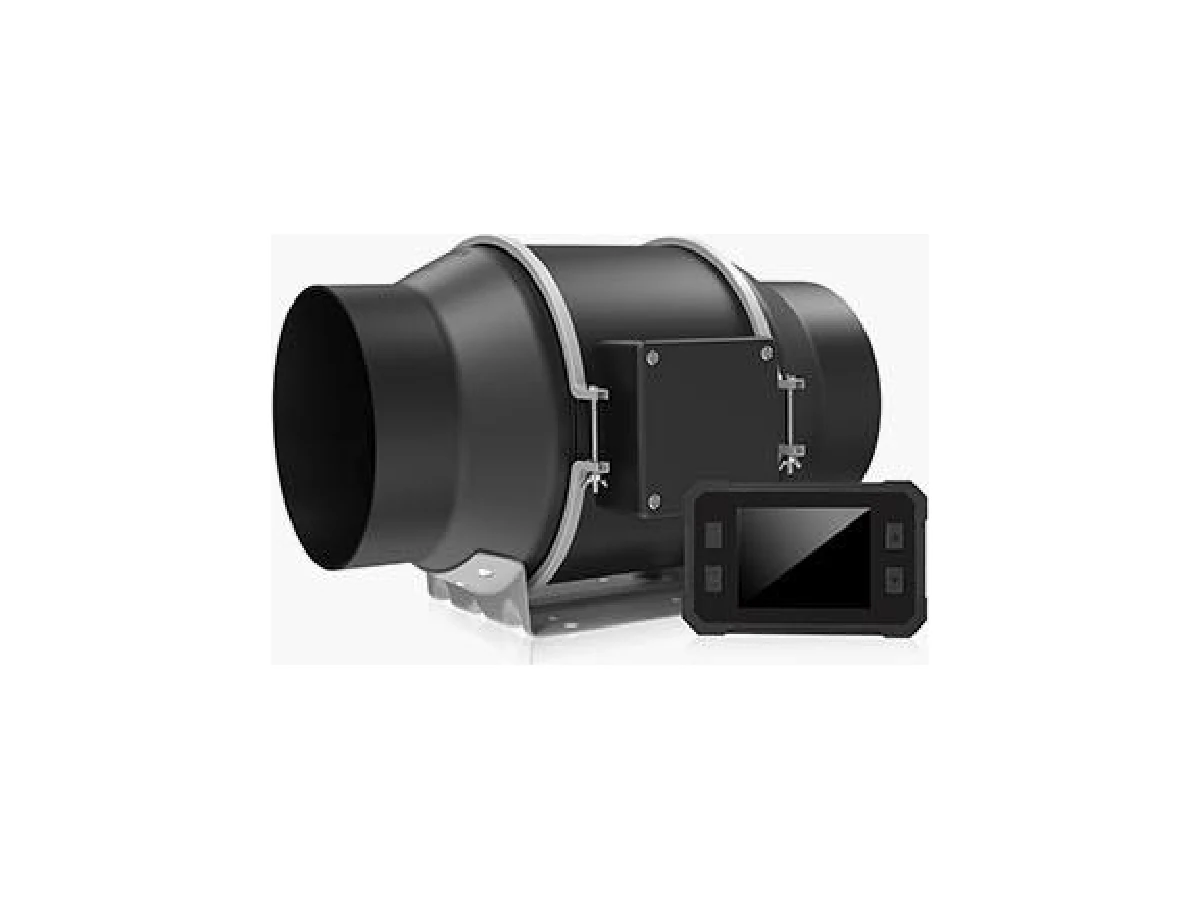
A fan system effect is the loss of usable fan performance caused by ductwork and airflow conditions near the fan. Elbows, abrupt transitions, dampers, obstructions, inadequate clearances and uneven inlet flow can add resistance or create turbulence, so a fan may deliver less airflow than its catalog curve suggests even when the motor is running at the expected speed.
What Fan System Effect Means and Why It Matters
Fan manufacturers normally test equipment under controlled laboratory conditions. The inlet and outlet connections are arranged to provide relatively uniform airflow, and the measured pressure, airflow, speed and power are recorded at defined points. An installed fan rarely operates in exactly those conditions.
When nearby duct geometry distorts the airflow entering or leaving the fan, the resulting performance change is called system effect. It may appear as an additional pressure loss, a change in the fan curve, higher noise, increased vibration, unstable operation or unexpected motor load. The fan itself may be correctly selected, but the connected system prevents it from reaching the expected duty point.
The problem is especially important for centrifugal fans. A poorly arranged inlet can produce swirl or uneven velocity across the impeller eye. A short, restrictive outlet connection can interfere with pressure recovery and create recirculation. Axial fans can also be affected when grilles, dampers, elbows or walls are placed too close to the inlet or discharge.
A useful distinction is that ordinary duct friction is part of the system resistance calculated during design. System effect is an additional penalty caused by local geometry and flow disturbance that may not be represented by standard straight-duct pressure-loss calculations. It should be considered during fan selection, layout review and commissioning.
For background on reading fan duty data, see Fan Technical Specs Explained: Airflow, Static Pressure and Power. The fan duty point should always be evaluated together with the connected duct system, not as an isolated catalog number.
Common Duct Conditions That Create System Effect
Several conditions repeatedly cause a gap between catalog performance and installed performance:
- An elbow installed immediately at the fan inlet or outlet
- A transition that changes size too quickly or is not centered on the fan connection
- An inlet duct that is smaller than the fan inlet or has a sharp offset
- A damper, grille, filter or screen located too close to the fan
- A flexible connector that is collapsed, misaligned or protruding into the airflow
- A discharge opening that releases air into a wall, roof curb or restricted plenum
- Multiple branch connections positioned close to the fan inlet
- A fan installed with insufficient clearance from a wall or adjacent equipment
- A sudden expansion or contraction that produces separation and recirculation
- A dirty filter, closed damper or obstructed screen that changes the operating point
An elbow changes the direction and velocity distribution of the air. If it is placed directly against a centrifugal fan inlet, the air may enter the impeller with uneven velocity or unwanted swirl. The impeller then has to correct a distorted flow pattern, which can reduce pressure development and increase sound or vibration.
Transitions are less disruptive when they are gradual, centered and aligned with the fan connection. An offset transition may be unavoidable, but its orientation should be reviewed carefully. An eccentric transition can create a high-velocity region on one side and a low-velocity or separated region on the other.
Dampers and other flow-control devices also create local losses. A damper that is partly closed near the fan can generate turbulence before the air reaches the impeller. The total pressure loss depends on the damper type, blade position, area and location. A damper is not automatically a problem, but it needs enough straight duct and should be sized for the required airflow.
The table below provides a practical first review.
| Condition | Likely effect | Recommended review |
|---|---|---|
| Elbow at inlet | Uneven velocity, inlet swirl, noise | Add straight length or a suitable turning arrangement |
| Abrupt transition | Separation and added pressure loss | Use a gradual, centered transition where space allows |
| Damper close to fan | Turbulence and unstable flow | Relocate it or provide better flow conditioning |
| Flexible connector protruding inward | Blockage and disturbed flow | Trim, align and tension the connector correctly |
| Restricted discharge | Poor pressure recovery and backpressure | Check outlet clearance, plenum area and discharge direction |
| Wall or obstruction near inlet | Nonuniform intake velocity | Increase clearance or install an appropriate inlet arrangement |
How Inlet and Outlet Layouts Affect Fan Performance
The inlet and outlet sides do not create identical problems. On the inlet side, the main concern is whether air reaches the impeller evenly and with the correct direction. On the outlet side, the concern is whether the high-velocity air can slow down and convert velocity pressure into useful static pressure without excessive turbulence.
For centrifugal fans, a straight approach section is usually beneficial. The exact length depends on fan geometry, airflow, duct size and the manufacturer’s installation guidance, so a universal clearance number should not be assumed. When a straight run is not possible, turning vanes, splitters or a properly designed inlet box may help, but these components must be selected and installed so they do not introduce a new obstruction.
The inlet connection should match the fan opening without a sharp lip, misalignment or sudden area change. A duct that is much smaller than the inlet can create a high-velocity jet entering one part of the impeller. A duct that is much larger may generate separated flow near the connection. Both conditions can reduce effective performance.
On the discharge side, a fan elbow should not force the air to turn immediately unless the fan and fitting arrangement has been evaluated for that condition. For a centrifugal fan, the discharge direction may also interact with the impeller rotation and housing geometry. The wrong turning direction or an excessively tight elbow can increase losses.
Axial fans require attention to inlet and outlet clearances because their airflow is more sensitive to obstructions and swirl. A protective grille, louver, damper or wall too close to the fan can reduce the effective flow area. Roof-mounted units also need sufficient discharge clearance so exhaust air does not recirculate back into the intake or nearby openings. Related layout issues are discussed in Roof-Mounted Exhaust Fans: Discharge, Weather and Access.
For mixed systems, inspect the whole local arrangement rather than focusing only on the fan flange. A fan may have a correctly sized connection while the next elbow, branch, silencer, filter or louver creates the actual restriction.
Estimating System Effect During Fan Selection
The most reliable approach is to identify system-effect risks before ordering the fan. Start with the required airflow, operating temperature, elevation, air density, pressure definition and control method. Then review the fan curve against the complete system resistance, including duct friction, fittings, filters, coils, dampers, grilles and process equipment.
Do not add an arbitrary pressure allowance without understanding the source of the loss. A general allowance may conceal a poor layout and make the fan larger than necessary. Instead, identify each local disturbance and request supplier guidance or a recognized system-effect method for estimating its penalty.
The following information should be available for a meaningful selection review:
- Required airflow at the actual operating condition
- Static pressure or total pressure requirement and measurement locations
- Air temperature, density, humidity and altitude where relevant
- Fan speed, motor rating and control range
- Fan inlet and outlet sizes
- Duct dimensions and the first major fitting on each side
- Distances from elbows, dampers, transitions and obstructions
- Filter, coil, louver, grille and silencer pressure losses
- Required sound, vibration, access and maintenance conditions
If the fan will operate at high altitude or with unusually hot air, correct the selection for air density. See Fan Selection at Altitude and Temperature: Correcting for Air Density for the variables that affect pressure, power and mass flow.
A specification should define the fan duty and the test or rating basis clearly. Check whether the quoted pressure is static pressure or total pressure, where the pressure is measured, and whether the rating assumes a particular inlet or outlet arrangement. Also confirm that the motor can handle the operating range, including possible changes in resistance after filters become dirty or dampers are adjusted.
If the layout is not finalized, provide the supplier with a drawing showing nearby fittings and clearances. A fan selected from airflow and pressure alone may not have enough margin for a severely disturbed connection, while a correctly arranged installation may require less capacity than a conservative but poorly defined allowance suggests.
Installation Practices That Reduce Performance Losses
Good installation begins with preserving the airflow conditions assumed during selection. The following practices reduce avoidable losses:
- Keep the fan, transition and duct centerlines aligned. Avoid forcing a flexible connection to correct a large mismatch.
- Provide a straight inlet approach where practical, especially before a centrifugal fan inlet.
- Keep elbows, dampers, filters and branch takeoffs away from the fan connections according to the equipment guidance and available system-effect data.
- Use gradual transitions with adequate length and avoid abrupt steps, sharp internal corners and unsupported flexible duct.
- Make sure flexible connectors are taut enough to remain stable but do not sag into the airflow or project beyond the fan opening.
- Check that dampers, louvers, screens and guards have sufficient free area for the required airflow.
- Support ductwork independently so its weight or thermal movement is not transferred to the fan casing.
- Seal leaks at flanges, access doors and flexible connections. Leakage changes delivered airflow and can make measured performance appear inconsistent.
- Confirm that the fan rotates in the correct direction and that belts, pulleys, guards and speed settings match the approved configuration.
- Leave access for filter replacement, damper adjustment, bearing inspection and cleaning. A difficult-to-service system often develops additional restrictions over time.
Do not assume that a larger motor will solve a system-effect problem. Increasing speed may raise airflow, but it can also increase noise, vibration, shaft load and energy use. If the fan is already near its power limit, a speed increase may overload the motor. A better correction is often to improve the inlet or outlet geometry, remove an obstruction or replace a restrictive fitting.
The same principle applies to control devices. Throttling a damper may reduce airflow, but it does not correct a badly disturbed fan inlet. For a comparison of airflow-control approaches, see Controlling Fan Airflow: Four Methods Compared.
Field Checks for Diagnosing System-Effect Problems
When measured airflow is below the design value, begin with basic operating checks before replacing the fan. Confirm the fan speed, rotation direction, motor frequency, damper position, filter condition and actual operating temperature. A wrong rotation direction, slipping belt or incorrect speed setting can produce symptoms similar to system effect.
Then inspect the local duct geometry. Look for an elbow immediately at the inlet, an offset transition, a collapsed connector, a blocked screen, a partially closed damper or a discharge directed into a nearby obstruction. Check whether the fan has been moved from the approved position or whether later duct modifications have shortened the approach or discharge path.
A practical field sequence is:
- Record fan speed, motor current, operating temperature and damper positions.
- Measure airflow using an appropriate method and document the measurement location and conditions.
- Measure static pressure or total pressure at defined points on the system.
- Compare the measured duty point with the fan curve at the actual air density and speed.
- Inspect inlet and outlet conditions, including clearances, transitions, elbows, filters, grilles and flexible connections.
- Temporarily correct or isolate the most obvious restriction where safe and permitted.
- Recheck airflow, pressure, current, noise and vibration after each controlled change.
- Decide whether the corrective action is a duct modification, control adjustment, cleaning task or fan replacement.
Pressure readings are only useful when the connection locations and instrument orientation are appropriate. A single pressure reading close to a turbulent elbow may not represent the average duct condition. Airflow measurements should also account for velocity-profile distortion and the limitations of the chosen instrument. More guidance is available in Commissioning: Measuring the Airflow You Actually Got.
Compare motor current carefully. High current with low airflow can indicate excessive resistance, incorrect rotation, high air density or a control problem. Low current with low airflow may indicate restricted inlet flow, a closed damper, belt slip, incorrect speed or a serious measurement error. Noise and vibration can support the diagnosis, but they do not identify the cause by themselves.
If corrective duct changes do not restore the expected duty, review the original selection. The required pressure may have been underestimated, the fan curve may have been interpreted incorrectly, or the operating condition may have changed. A replacement fan should be considered only after the system resistance and installation geometry have been verified.
FAQ
Is fan system effect the same as duct friction?
No. Duct friction is the normal resistance of straight duct and fittings and should be included in the system curve. Fan system effect describes additional performance loss caused by disturbed flow near the fan, such as inlet swirl, uneven velocity or inadequate discharge recovery.
How much straight duct does a fan need?
There is no single clearance value that applies to every fan. The required arrangement depends on fan type, inlet geometry, duct size, airflow, fittings and the manufacturer’s rating basis. Use the approved installation guidance and review any nearby elbow, damper or transition as a potential system-effect source.
Can a larger fan overcome system effect?
It may deliver more airflow, but it can also increase noise, energy use, vibration and motor loading. A larger fan does not correct disturbed inlet flow or a badly arranged discharge. Improving the duct geometry is usually the first corrective step.
Why does airflow fall after a fan is installed even though the fan matches the catalog rating?
Catalog ratings are based on defined test conditions. The installed system may have additional resistance from elbows, transitions, dampers, filters, obstructions, leakage or poor clearances. Verify speed, rotation, pressure measurement locations and duct geometry before changing the fan.
When should the supplier review the installation drawing?
Ask for a review whenever the fan has a short inlet or discharge connection, multiple nearby fittings, a tight equipment room layout, an unusual transition, a roof curb or a high-resistance process application. Supplying the complete local layout helps the supplier assess whether the selected fan rating matches the actual installation.